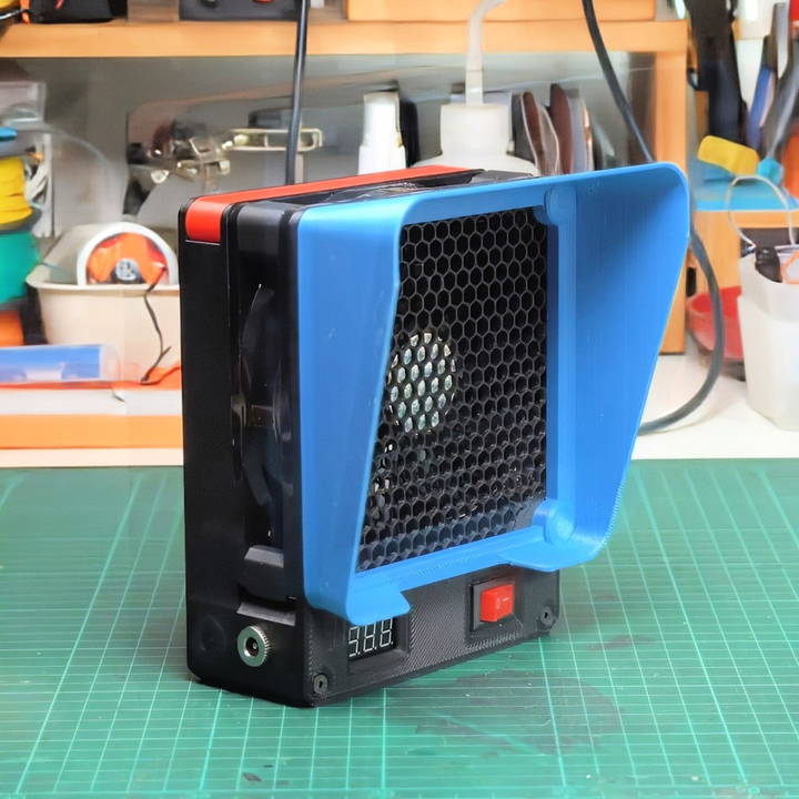
Making your own DIY fume extractor can transform your workspace into a safer, cleaner, and more efficient environment. For electronics enthusiasts, makers, and anyone regularly working with solder, a fume extractor is essential to safeguard against the harmful fumes generated during soldering. This guide provides detailed, step-by-step instructions on building an all-in-one DIY fume extractor with a USB-C power hub, magnetic hood, and quick-access carbon filter. Let's dive into the materials, tools, steps, and tips needed to make this project.
Why Build a Fume Extractor?
When working with solder, toxic fumes, such as lead and flux vapors, are released. A fume extractor pulls these hazardous fumes away from your face and work area, capturing them in a filter to prevent inhalation. By making a custom DIY solution, you not only save on costs but also tailor the features to your exact requirements, adding flexibility and usability.
Key Features of the DIY Fume Extractor
This DIY fume extractor is built to be multifunctional and user-friendly with unique elements that make it stand out:
- Powered by an Old 120mm PC Fan: Reuse a standard 120mm PC fan, an affordable and accessible choice.
- USB-C Power Hub: Integrates USB-C compatibility for modern charging and powering options.
- Magnetic Hood: Easily attach and detach the hood using small magnets.
- Carbon Filter Bay: A dedicated slot for carbon filters with a simple latch for easy access and replacement.
- Voltage Display: An LCD voltmeter that displays the main input voltage, enabling real-time monitoring of your setup.
- DC Power Forwarding: Extra DC outlets let you power additional devices, like a portable soldering iron, directly from the fume extractor.
Materials and Tools Needed
Before getting started, gather the following components, tools, and materials. You'll find these items readily available online or at your local electronics store.
Components
- 120mm PC Fan: Serves as the primary mechanism for air movement.
- Buck Converter: Used to adjust the power input range (recommended range: 10-23V).
- USB-C Power Delivery Module: Allows modern USB-C chargers to power the fan and other devices.
- LCD Voltmeter: Displays the input voltage, aiding in safe and consistent power monitoring.
- DC Sockets: Two sockets for the DC power forwarding function.
- Carbon Filter: 12x12 cm, 1 cm thick; helps trap harmful particles.
- Magnets: 5mm diameter magnets for the detachable hood.
- M4 and M3 Screws: Various sizes for securing components.
Tools
- 3D Printer: For printing the case and hood components (files available online).
- Soldering Kit: For connecting wires and assembling components.
- Crimping Tool: Useful for attaching connectors to the fan wires.
- Volt Meter: Essential for measuring voltage during setup.
- Epoxy Glue: For securing magnets in the hood.
- Drill and Sandpaper: To smooth and widen 3D-printed parts if necessary.
Step by Step Instructions
Learn to make a DIY fume extractor with our step-by-step guide, from 3d printing parts to wiring and installing a carbon filter efficiently.
Step 1: Preparing the 3D-Printed Parts
Start by printing the components designed specifically for this fume extractor, including the main case, detachable hood, and other parts for mounting. Follow these steps:
- Insert M4 Hot Melt Insert Nuts: Position four nuts in the main case's center part and two on the back cover.
- Prepare Slots for Magnets: Drill or sand down any tight holes for the magnets in the hood if needed.
- Smooth Edges: Use a rotary tool or sandpaper to remove any sharp edges or rough overhangs on printed parts.
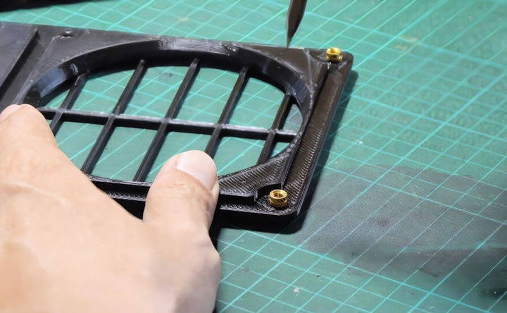
These printed parts form the backbone of your fume extractor, so ensure they fit and are durable.
Step 2: Modifying and Wiring the PC Fan
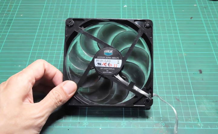
The 120mm fan will be the core of the fume extractor. Here's how to modify and wire it:
- Identify Fan Wires: Locate the ground wire (typically black) and the V+ wire for power.
- Replace Molex Connector: If the fan has a Molex connector, replace it with a 2-pin JST connector for better compatibility.
- Cut Unused Signal Wire: If your fan has an unused signal wire, cut it to prevent interference.
- Crimp JST Connectors: Attach the JST connectors to the fan wires. Crimp the male connector to the wires for the buck converter output to facilitate power flow from the converter to the fan.
Step 3: Setting Up and Calibrating the Buck Converter
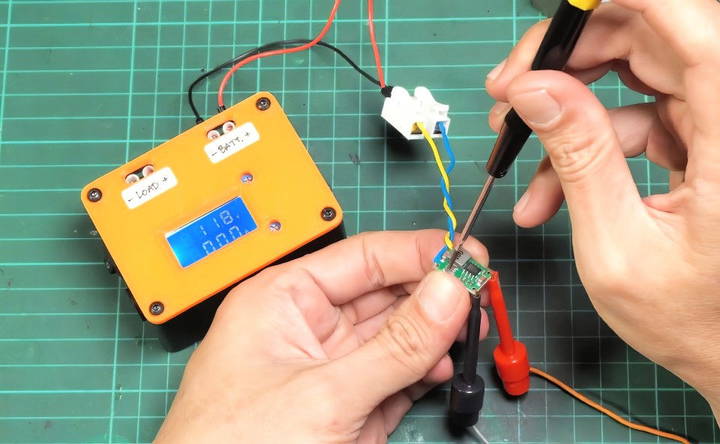
The buck converter lets you use various power sources, such as a Makita battery or other standard adapters. Here's how to set it up:
- Connect Wires to Buck Converter: Attach crimped wires to the converter's output. The positive wire goes to the rocker switch, while the negative connects to the main input.
- Calibrate Output Voltage: Connect the buck converter to a power supply and measure the output with a voltmeter. Adjust the potentiometer until the output reads around 12 volts to ensure compatibility with the fan.
Use VHB tape to secure the buck converter to the fan case, keeping it firmly in place during operation.
Step 4: Wiring the LCD Voltmeter
The voltmeter is an essential feature for voltage monitoring. Here's how to install it:
- Trim Extra Wire: If your voltmeter has a third (yellow) wire, cut it off as it won't be used in this setup.
- Mount the Voltmeter: Insert the meter into its designated slot in the case. Secure it with two M3 screws.
This display lets you monitor the power status, ensuring your fume extractor runs safely and efficiently.
Step 5: Installing the Rocker Switch and PD Trigger Board
The switch controls power to the fan, while the PD trigger board manages USB-C input:
- Wire Rocker Switch: Solder a wire to the switch pin for input from the power socket, and connect another pin to the buck converter's input positive.
- Bridge PD Trigger Board Jumper: To support 20V, bridge the jumper on the PD trigger board.
- Add Diode for Safety: Connect a diode to prevent reverse current. Attach the positive pin to the board output, ensuring the grey strip on the diode faces outward.
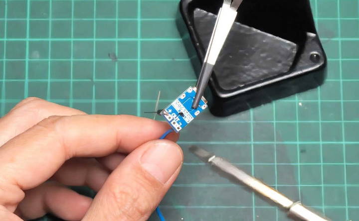
Attach the PD board securely to the case with VHB tape for stable positioning.
Step 6: Connecting DC Sockets
Two DC sockets are provided for extra connectivity options. Follow these steps:
- Solder Connections: Connect the positive wire to the center pin of each DC socket and the negative wire to another pin. Cover each pin with a shrink tube for protection.
- Mount Sockets to Case: Place the nuts into the slots, insert the sockets, and tighten them with pliers.
These DC outlets allow you to power additional devices from your fume extractor, making it a versatile workbench tool.
Step 7: Final Wiring and Assembly
Now it's time to connect everything with a screw terminal block and complete the assembly:
- Wire the Screw Terminal Block: Connect the positive wires from the USB-C board, left DC socket, and switch. Repeat for the negative wires, and mark positive poles with a red marker.
- Organize Wiring: Secure wires with cable ties to keep them neat and prevent tangling.
- Attach Fan to Case: Position the fan within the case and secure it with M4 screws. Insert shims as needed for a snug fit.
- Secure Back Cover: Use screws to attach the back cover, ensuring all components are enclosed.
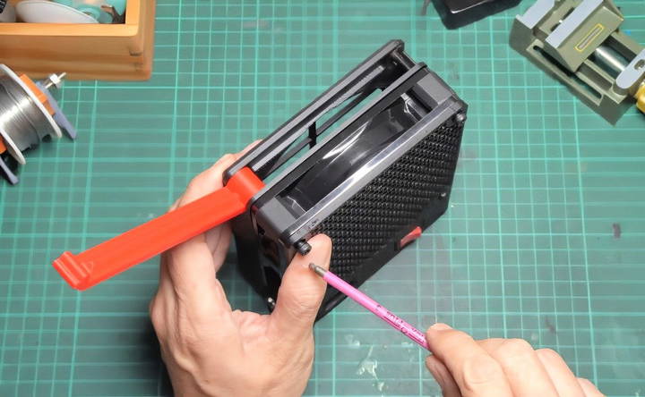
With the main wiring complete, your fume extractor is nearly functional.
Step 8: Preparing and Installing the Carbon Filter
The carbon filter captures fumes as air passes through. Here's how to set it up:
- Cut Filter to Size: Cut a 12x12 cm square from the carbon filter sheet, about 1 cm thick.
- Insert Filter into Bay: Place the filter within the bay, securing it with the latch.
Replacing this filter periodically will maintain optimal air quality at your workstation.
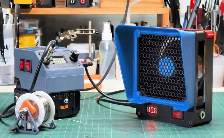
Step 9: Adding the Magnetic Hood
The detachable hood allows you to focus the airflow:
- Attach Magnets: Insert magnets into the pre-drilled holes on the hood. Secure them with epoxy glue for durability.
- Align Hood with Case: Align the hood with the fan case. The magnets will hold it in place firmly, allowing easy attachment and detachment.
Tips and Safety Considerations
- Power Supply Compatibility: Use a power supply that delivers a voltage higher than the fan's requirement to ensure efficient operation.
- Monitor Voltage Regularly: The built-in voltmeter helps prevent power surges by allowing real-time voltage monitoring.
- Check DC Outlets: Ensure the extra DC outlets are only used for devices compatible with the main input voltage, as they aren't regulated.
Conclusion
Building a DIY fume extractor is not only rewarding but also essential for a healthier workspace. With features like a USB-C power hub, magnetic hood, and replaceable carbon filter, this project is a versatile addition to any maker's workbench. By following these steps, you'll have a powerful fume extractor tailored to your needs. Happy building, and breathe easy!
FAQs About DIY Fume Extractor
Discover answers to FAQs about DIY fume extractors. Learn how to build, use, and maintain your device for optimal safety and efficiency.
For this project, 20 AWG wires are suggested as they provide a balance between flexibility and durability, ensuring safe and efficient power flow to the fan, buck converter, and other modules.
The carbon filter is effective for capturing toxic volatile organic compounds (TVOCs) but is less effective for flux particles. If you frequently solder with flux-heavy applications, consider a HEPA filter, as it’s better at capturing smaller particles.
Placing the filter in front of the fan might reduce airflow efficiency slightly, but it can protect the fan from sticky flux residues. This setup can keep the fan cleaner over time, though it may need a stronger fan to maintain airflow.
If double-sided tape alone is insufficient, you can reinforce it with a layer of hot glue on top for extra stability. This provides additional strength and prevents the board from shifting inside the case.
The diode is used to prevent backflow of current to the USB-C PD port, essential when using a DC input. A Schottky diode could be used for a lower voltage drop, but the 1N4007 diode was chosen for availability and reliability.
The current design is optimized for a 120mm fan. To use a 140mm fan, modifications would be needed, such as adjusting the 3D print files for compatibility with the larger fan dimensions.
Yes, the top latch is included in the downloadable 3D print files. If you're missing it, ensure you have the latest version of the files, as it was added after initial feedback.
Printing all parts generally takes around two days, depending on printer settings. Assembly time varies, but many users complete it within a few hours, factoring in wiring and testing time.
Yes, a regular 12V fan can be used, but it may not provide the same power output as more robust fans designed for continuous operation in fume extraction applications.
The voltage display allows users to monitor the input voltage, helping to prevent power issues by ensuring compatible input voltage is provided to each component.


